Latest Posts
Favourite Posts
Wave Equation Formulations
For systems described by the wave equation in 1d there are three equivalent ways to describe the system. This post explains them and covers their relation to various types of boundary conditions we typically want to apply. It is part of the theory behind the simulation in the post “Interactive Linear Shallow Water Simulation”.
Contents
Formulations in 1D
The wave equation in one dimension reads
$$\ppfrac{y}{t} - c^2 \ppfrac{y}{x} = 0$$It is a second order partial differential equation, meaning that in order to fully describe the state of a system we must specify the value of the function $y$ and its time derivative $\dot y$. Thus, any initial and boundary conditions we want to specify must also be in terms of $y$ and $\dot y$. The meaning of $y$ is clear, but to tie $\dot y$ to something more interpretable we can seek alternative descriptions of the system and then relate these back to $\dot y$.
One-way Wave Equations
The 1d wave equation can be factored as
$$\Big(\pfrac{}{t} - c\pfrac{}{x}\Big)\Big(\pfrac{}{t} + c\pfrac{}{x}\Big)y = 0$$which is the product of the left- and right-moving 1d advection operators, both with velocity $c$. A right-moving solution \(y = g(x - ct)\) is a solution to the rightward 1d advection equation:
$$\Big(\pfrac{}{t} + c\pfrac{}{x}\Big)g(x - ct) = -cg^\prime(x - ct) + cg^\prime(x-ct) = 0$$We are free to choose the order of the application of the left- and rightwards advection operators because they commute (because the partial derivatives commute.) This means the solution to the right-moving advection equation must also be a solution of the wave equation. We can see this is true because we can apply the right-moving advection operator first, and squash it to zero, leaving the left-moving with only zero to operate on.
The leftwards operator will change the right-moving solution, but it remains a right-moving solution:
$$\Big(\pfrac{}{t} - c\pfrac{}{x}\Big)g(x - ct) = -cg^\prime(x - ct) - cg^\prime(x-ct) = -2cg^\prime(x - ct)$$This must be true, since the operators commute and if the leftwards operator gave a non right-moving solution, then we wouldn’t get zero as the wave equation says we must.
Obviously, the same argument works for the left-moving solution.
Because the wave equation is linear, valid solutions are superpositions of left- and right-moving waves (in 1d). Thus a generic solution to the 1d wave equation is
$$y(x, t) = f(x + ct) + g(x - ct) \label{wave_eqn_soln}\tag{1}$$To connect this description back to $\dot y$ we can just differentiate it wrt time
$$\begin{align} \pfrac{y}{t} &= \pfrac{f(x+ct)}{t} + \pfrac{g(x - ct)}{t} \\[0.5em] &= cf^\prime(x+ct) - cg^\prime(x-ct) \end{align}$$This gives us a way to specify our system in terms of $y$ and $\dot y$ but have it display the desired left-/right-moving behaviour.
Here’s a visualization of two left- and right- moving waves and their sum, as well as the time derivative. Drag the sliders to control time, and the respective magnitudes of the left- and right-moving waves.
Density & Velocity
We can also describe the system via the function itself $y$ and an auxiliary velocity field $u$, which are governed by two coupled first order differential equations.
$$\begin{align} \pfrac{y}{t} = c\pfrac{u}{x} \label{first_order_y}\tag{2}\\[0.5em] \pfrac{u}{t} = c\pfrac{y}{x} \label{first_order_u}\tag{3} \end{align}$$The proof that this yields the wave equation is simple, we can just differentiate equation \eqref{first_order_y} wrt time, then use equation \eqref{first_order_u}:
$$\begin{align} \pnfrac{y}{t}{2} = c\pfrac{}{t}\pfrac{u}{x} = c\pfrac{}{x}\pfrac{u}{t} = c^2\pnfrac{y}{x}{2}\qquad\square \end{align}$$Since the equations are symmetric, it’s clear that $u$ is also governed by the wave equation. In this interpretation $y$ can be seen to be a density and $u$ is its flux (or current).
In the post on the shallow-water equations we saw that $y$ was equivalent to the shallow fluid’s height, and $u$ was the fluid’s average horizontal velocity. Similarly, the homogeneous linearized shallow-water equations are exactly equivalent to the equations describing the propagation of density perturbations in a quiescent compressible fluid (see). In this case $y$ is literally the fluid’s density and $u$ its velocity.
What’s the relationship between the velocity $u$ and the left- and right-moving components; $f$ and $g$ respectively? Just substitute in equation \eqref{wave_eqn_soln} to equations \eqref{first_order_y} and $\eqref{first_order_u}$.
$$\begin{align} \pfrac{u}{x} &= \frac{1}{c}\pfrac{}{t}\Big(f(x+ct) + g(x-ct)\Big) = f(x+ct) - g(x-ct) \\[0.5em] \pfrac{u}{t} &= c\pfrac{}{x}\Big(f(x+ct) + g(x-ct)\Big) = c f(x+ct) + c g(x-ct) \end{align}$$We can see from inspection that this implies
$$u = f(x+ct) - g(x-ct)$$As expected this is also a solution to the wave equation, simply with the sign of the right-moving wave flipped.
Let’s look at the velocity on the visualization:
Boundary Conditions
Usually we want to specify one of 3 types of boundary conditions:
- Reflecting (inverting)
- Reflecting (non-inverting)
- Non-reflecting
Imagine we have a boundary at the origin, \(x=0\) with a left-moving wave approaching it from the right. Let’s examine the three types of boundary conditions.
Reflecting (inverting)
The first type of boundary, reflecting (inverting), is achieved by setting $y$ to be fixed at the boundary; $y(0, t) = 0$. To understand why the reflected wave gets inverted we can imagine the following scenario. Picture a fictitious right-moving wave, which mirrors the left-moving wave’s approach to the boundary, but has opposite sign. The two waves will exactly cancel at the origin ensuring $y = 0$.
Mathematically we are saying $g(x-ct) = -f(-(x-ct))$, which gives $y = f(x+ct) - f(ct-x)$. At $x=0$ we get $y(x=0) = f(ct) - f(ct) = 0$ as desired.
Further, the part of the left-moving wave that has moved past the origin becomes part of the “fictitious” image, and similarly the right-moving part in the domain becomes “real”. Because the right-moving image had inverted sign to ensure $y = 0$, the reflected wave is inverted in sign.
If we are implementing a simulation in terms of the left- and right-moving components $f$ and $g$ respectively, then this boundary condition is equivalent to setting the right-moving component to be $g(0, t) = -f(0, t)$. If we are implementing things in terms of $y$ and $\dot y$, then it’s exactly setting $y(0, t) = 0$, which also implies $\dot y(0, t) = 0$. Finally, if we are implementing things in terms of $y$ and $u$ then this boundary condition implies we have $\partial_x u = 0$ from equation \eqref{first_order_y} and the fact $\partial_t y = 0$.
Reflecting (non-inverting)
The second type of boundary, reflecting (non-inverting), is achieved by fixing the $x$-gradient at the boundary; $\partial_x y(0, t) = 0$ and leaving $y$ free to vary. Here we can imagine a similar fictitious mirrored right-moving wave, but this time it receives the same sign as the left-moving wave, thereby ensuring zero gradient at the boundary.
In this case we are requiring $g(x-ct) = f(-(x-ct))$ so $y(x, t) = f(x+ct) + f(ct-x)$, yielding
$$\pfrac{y}{x} = f^\prime(x+ct) - f^\prime(ct-x)$$which is equal to zero at $x=0$ as required.
Again, once the left-moving wave moves past the boundary it becomes fictitious, and the right-moving image become real once it is past the boundary and inside the domain. This time, because the right-moving image received the same sign as the left-moving wave, the reflection is not inverted.
If implementing in terms of $f$ and $g$ then setting $\partial_x y(0, t) = 0$ is equivalent to requiring $g(0, t) = f(0, t)$, as we have seen. From the velocity standpoint it’s equivalent to requiring $u(0, t) = 0$ because we know $u = f - g$.
Non-reflecting
Often for our simulations we actually won’t want any reflection from the boundary. For this case we can require that the boundary obeys the appropriate one-way wave equation. In our example we have a left-moving wave approaching a boundary at the origin, so at the boundary we require
$$\pfrac{y}{t} (0, t) - c \pfrac{y}{x} (0, t) = 0 \label{bc_non_reflecting_y}\tag{4}$$which is directly specified in terms of $\dot y$. Note that the value of $y$ is also fixed by these since it has to obey $y = \int_0^t \dot y dt + y(0, 0)$. In this case there is no right-moving component so we have simply $g(0, t) = 0$.
If we are describing the system in terms of $y$ and $u$, then we can just substitute equations \eqref{first_order_y} and \(\eqref{first_order_u}\) into the boundary condition (i.e. the left-moving advection equation), yielding
$$\pfrac{u}{t}(0, t) - c\pfrac{u}{x}(0, t) = 0 \label{bc_non_reflecting_u}\tag{5}$$The velocity $u$ also just follows the left-moving advection equation. This is not surprising given the symmetry of equations \eqref{first_order_y} and \(\eqref{first_order_u}\).
Note that the boundary conditions here are in terms of $\partial_t y$ and $\partial_t u$, but using $u$ lets us describe the system as two coupled first order equations, so we cannot directly set the time derivatives in any simulations we might run. To achieve these boundary conditions in a simulation we can update the stored values of $y(0, t)$ and $u(0, t)$ using suitably discretized versions of equations \eqref{bc_non_reflecting_y} and \(\eqref{bc_non_reflecting_u}\).
Visualization
Looking at each type of boundary condition on our visualization, we can get a very intuitive sense of what the maths is describing:
Higher Dimensions
In dimensions higher than 1 we clearly can’t use the left-/right-moving description of the system, because there are infinite directions a wave front could be moving in.
However the description in terms of the velocity generalizes simply; the velocity becomes a vector matching the dimension of the system we are interested in.
The first order equations are
We can see easily that $y$ is still governed by the wave equation:
$$\begin{align} \pfrac{}{t} \pfrac{y}{t} &= \pfrac{}{t}\Big(c \nabla \cdot \mathbf u\Big) \\[0.5em] &= c \nabla \cdot \pfrac{\mathbf u}{t} \\[0.5em] &= c^2 \nabla \cdot \nabla y \\[0.5em] &= c^2 \nabla^2 y\qquad\square \end{align}$$In this case \(\mathbf u\) is governed by an equation which looks quite a lot like the wave equation, but which mixes the components via the divergence:
$$\begin{align} \pfrac{}{t} \pfrac{u}{t} &= \pfrac{}{t}\Big(c \nabla y\Big) \\[0.5em] &= c\nabla \pfrac{y}{t} \\[0.5em] &= c^2 \nabla( \nabla \cdot \mathbf u) \end{align}$$Boundary Conditions
The three types of boundary conditions discussed above are simple enough to write down in higher dimensions; we just need to account for the boundary’s normal vector. Their specification is shown in the table below, where the normal unit vector $\hat{\mathbf n}$ points into the domain.
| Boundary Condition | Second Order | Density & Velocity |
|---|---|---|
| Reflecting (inverting) | $y=0$ | $\hat{\mathbf n} \cdot \nabla u = 0$ |
| Reflecting (non-inverting) | $\hat{\mathbf n} \cdot \nabla y = 0$ | $u = 0$ |
| Non-reflecting | $\partial_t y = c \hat{\mathbf n} \cdot \nabla y$ | $\partial_t y = c \hat{\mathbf n} \cdot \nabla y$ $\partial_t u = c \hat{\mathbf n} \cdot \nabla u$ |
Publications
During my undergrad, masters and PhD studies I published a few articles with several co-authors & collaborators. Here’s a list of articles where I am included as an author:
- Finite size scaling of the spontaneous symmetry breaking model of X-chromosome inactivation - D. Barker & A. Griffiths, March 2009.
- MC4: a tempering algorithm for large-sample network inference - Daniel James Barker, Steven M. Hill & Sach Mukherjee, September 2010.
- SPH Simulation of Packed-beds and Columns Applied to Heap-leaching - Barker, D.J., Parameswaran, G. & Neethling, S.J., December 2012.
- Predicting fluid flow and mass transfer in heaps using SPH - D.J. Barker & S.J. Neethling, June 2013.
- Application of B-splines and curved geometries to boundaries in SPH - Daniel J. Barker, Pablo Brito-Parada, Stephen J. Neethling, July 2014.
- The application of smoothed particle hydrodynamics to the simulation of multiphase flows through packed beds (PhD Thesis) - Daniel James Barker, September 2014.
- Using Smoothed Particle Hydrodynamics to Model Multiphase Mineral Processing Systems - Stephen J. Neethling, Daniel J. Barker, October 2015.
- Modelling particle scale leach kinetics based on X-ray computed micro-tomography images - Q. Lin, D.J. Barker, K.J. Dobson, P.D. Lee, S.J. Neethling, June 2016.
- Standard method for performing positron emission particle tracking (PEPT) measurements of froth flotation at PEPT Cape Town - Katie Cole, Daniel J. Barker, Pablo R. Brito-Parada, Andy Buffler, Kathryn Hadler, Isobel Mackay, Diego Mesa, Angus J. Morrison, Stephen Neethling, Alexander Norori-McCormac, Barry Shean, Jan Cilliers, March 2022
It’s unlikely this list will ever grow, given I’ve not been even close to academia since finishing my doctorate. However, if by some off chance it does grow, I’ll be sure to update it.
Interactive Linear Shallow Water Simulation
This is an interactive simulation of the linearized shallow-water equations. For info on the the equations themselves, see the last post Deriving the Shallow Water Equations. The simulation uses WebGPU to accelerate both the simulation and the rendering. I will discuss these below, but without further ado here’s the simulation:
Click on the canvas below, then click "Start"...
The simulation has varying bathymetry with the water becoming shallower towards the right-hand edge of the domain, like a beach.
Numerical Method
The numerical method is a simple finite difference simulation. It uses central differences for the spatial derivatives, and the improved Euler method for time-stepping. The full update rules are verbose, but simple. Expand the box below to view them if you’re interested.
We implement the computation as WebGPU compute shaders. These shaders cannot see updated values from array indices other than our own until the end of the pipeline. However, our final value computation requires knowing the value of the intermediate value at neighbouring points. Because of these two facts, we have to split our intermediate & final value calculations into two separate shaders. With a third handling the setting of the boundary condition values.
If we naively split our computation just as they are written above, we may think we need two sets of intermediate arrays; one for the intermediate values, and one for the corresponding “deltas”:
$$\begin{align} \Delta y_{t} &= f(y_t)\Delta t \\[0.2em] \tilde y_{t+1} &= y_t + \Delta y_t \label{impeul1}\tag{1} \\[0.2em] \Delta\tilde y_{t+1} &= f(\tilde y_{t+1})\Delta t \\[0.2em] y_{t+1} &= y_t + (\Delta y_t + \Delta \tilde y_t) / 2 \\[0.2em] \end{align}$$However, we can eliminate \(\Delta \tilde y\) by substituting in equation \eqref{impeul1}, so
$$\begin{align} y_{t+1} &= y_t + (\Delta y_t + f(\tilde y_{t+1})\Delta t) / 2 \\ &= y_t + (\tilde y_{t+1} - y_t + f(\tilde y_{t+1})) / 2 \\ &= y_t + \tilde y_{t+1} /2 - y_t / 2 + f(\tilde y_{t+1})\Delta t / 2 \\ &= (1/2) (y_t + \tilde y_{t+1} + f(\tilde y_{t+1})\Delta t) \end{align}$$Thus we only need to keep around the intermediate value, and not the original gradient which was used to calculate it.
Because I am using central differences I do not update the outer edges of the simulation domain, using these, instead, to set the boundary conditions.
Boundary Conditions
There are two types of boundary conditions used for this simulation; (non-inverting) reflecting and non-reflecting.
- Reflecting
- \(\partial_y \eta = 0\,\) and \(\,\partial_y \mathbf u = 0\,\) along the horizontal boundaries.
- \(\partial_x \eta = 0\,\) and \(\,\partial_x \mathbf u = 0\,\) along the right-hand vertical boundary.
- Non-reflecting:
- \(\partial_t \eta = c \partial_x \eta\,\), \(\,\partial_x u = -\frac{1}{bc} \partial_x \eta\,\) and \(v=0\) along the left-hand vertical boundary.
The reflecting boundaries are enforced by setting the outermost cell values s.t. the central differences are zero.
The non-reflecting boundary conditions correspond to the equations satisfied by a purely left-moving wave. They are enforced by adding values to the leftmost cell values corresponding to the discretization of this equation:
$$\Delta \eta_{0,j} = c\,(\eta_{1,j} - \eta_{0,j}) \frac{\Delta t}{\Delta x}$$and similarly for \(u\). This is the most simple, first order, discretization of the left-moving advection equation. I’m sure there are more accurate ways to calculate this.
Rendering
The rendering is also handled by a WebGPU shader. There are two steps, which are both relatively simple, that get combined into the final image. First, I model the effect of the depth of the water on the colour we expect to see; for very shallow water we see the yellow of the beach, whereas for deeper water we see only the dark blue of the water itself. Second I add specular reflections of the water’s surface using Phong lighting.
The rendering of the sand is pretty simple; I define a base colour for the sand (#beba00) and the water (#4eb2ff), then I blend them depending on the depth of the water. The blending is exponential, following the Beer-Lambert law. Because water absorbs red light much more strongly than green or blue we apply a different exponential decay for the red, green and blue channels. Thus the final colour is given by
$$\text{Sand}_c\cdot e^{-\lambda_c h} + \text{Water}_c\cdot \big(1-e^{-\lambda_c h}\big) $$for \(c\in \{R, G, B\}\) and $\lambda_R=\lambda_G=2\lambda_B$. These particular values of the decay coefficients aren’t at all physically realistic, but they look okay.
Then, using the formula in the derivation post, we can calculate the normal vector to the surface. This lets us apply the formulas for Phong lighting, as detailed on Wikipedia, to get the specular & diffuse lighting for the water’s surface.
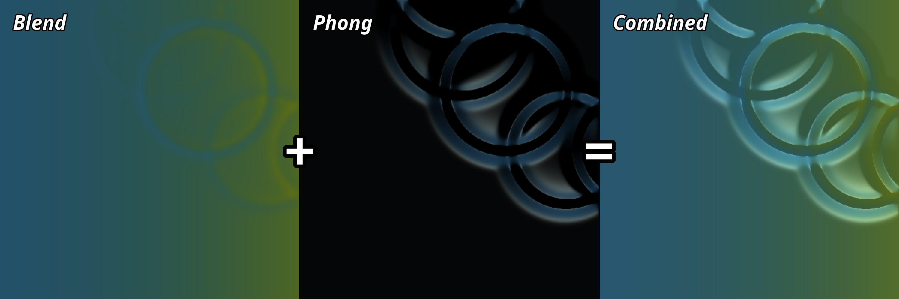
The rendering is implemented as a fragment shader, which renders onto a single triangle covering the whole viewport.
This is initialized with a very simple vertex shader.
The WebGPU shader code for this simulation can be found here.
(Warts debug lines and all)